Hole & Shaft Tolerances Deviations And Fits – ISO 286
Designation of the tolerance class
General
The tolerance class shall be designated by the combination of an upper-case letter(s) for holes and lowercase letters for shafts identifying the fundamental deviation and by the number representing the standard tolerance grade.
EXAMPLE (ISO 286): H7 (holes), h7 (shafts). “H” and “h” indicate the tolerance position, while “7” represents the tolerance grade.
Size and its tolerance
A size and its tolerance shall be designated by the nominal size followed by the designation of the required tolerance class (ISO 286), or shall be designated by the nominal size followed by + and/or − limit deviations (see ISO 14405).
In the following examples the indicated limit deviations are equivalent to the indicated tolerance classes.
EXAMPLE:
ISO 286
ISO 14405
32 H7
32
+0.025
0
80 js15
80 ± 0.6
100 g6
100
-0.012
-0.034
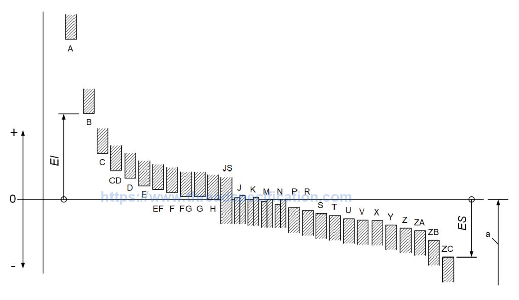
Figure 1: Hole tolerance position
Hole tolerance deviations: A, B, C, CD, D, E, EF, F, FG, G, H, JS, J, K, M, N, P, R, S, T, U, V, X, Y, Z, ZA, ZB, ZC.
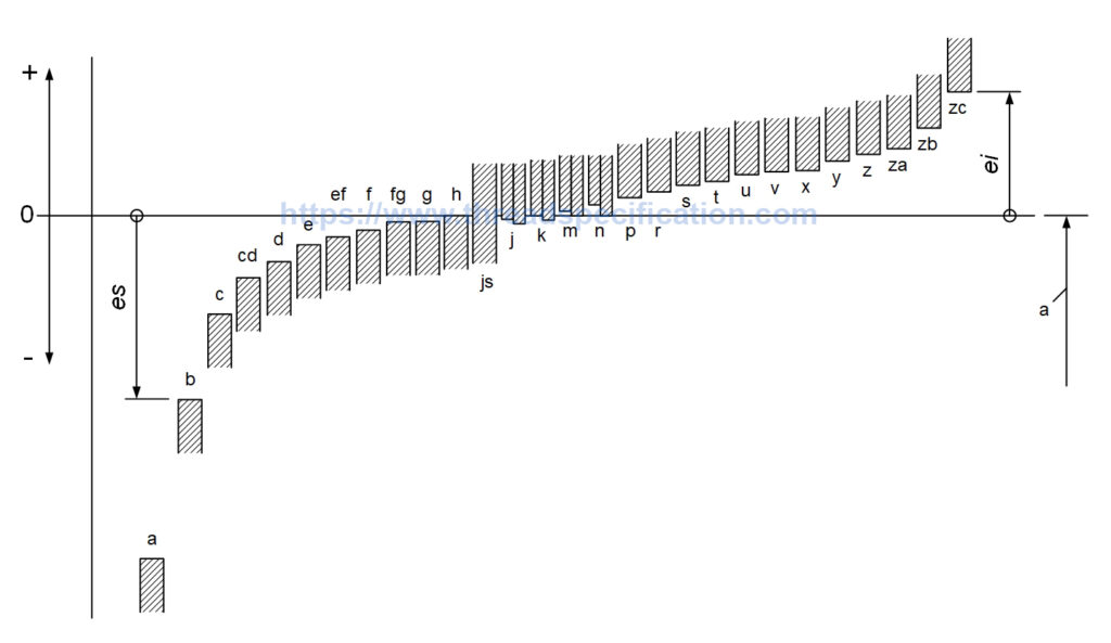
Figure 2: Shaft tolerance position
Shaft tolerance deviations: a, b, c, cd, d, e, ef, f, fg, g, h, js, j, k, m, n, p, r, s, t, u, v, x, y, z, za, zb, zc.
Selection of tolerance classes
Whenever possible, the tolerance classes should be chosen from those corresponding to the classes for holes and shafts given in Figures 3 and 4, respectively. The first choice should preferably be made from the tolerance classes, shown in the frames.
The tolerance classes of Figures 3 and 4 apply only to general purposes which do not require a more specific selection of tolerance classes. Keyways, for example, require a more specific selection.
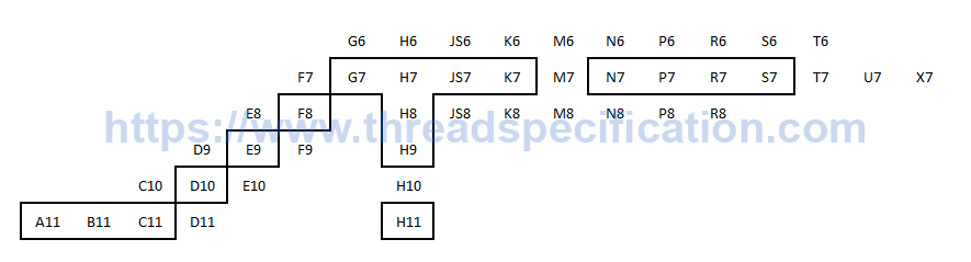
Figure 3: Hole tolerance class selection
General purposes hole tolerance class: A11, B11, C10, C11, D9, D10, D11, E8, E9, E10, F7, F8, F9, G6, G7, H6, H7, H8, H9, H10, H11, JS6, JS7, JS8, K6, K7, K8, M6, M7, M8, N6, N7, N8, P6, P7, P8, R6, R7, R8, S6, S7, T6, T7, U7, X7.
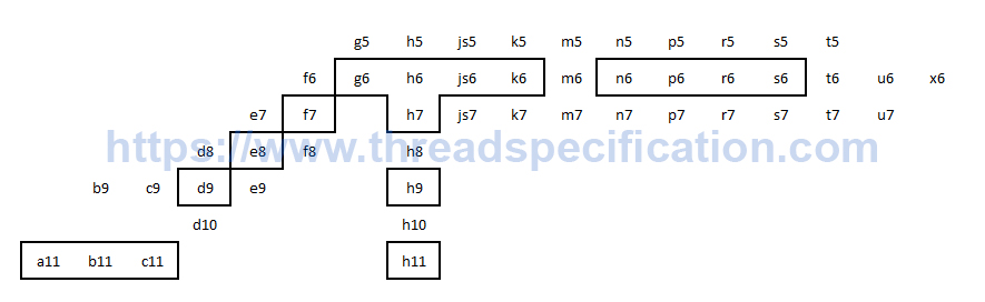
Figure 4: Shaft tolerance class selection
General purposes shaft tolerance class: a11, b9, b11, c9, c11, d8, d9, d10, e7, e8, e9, f6, f7, f8, g5, g6, h5, h6, h7, h8, h9, h10, h11, js5, js6, js7, k5, k6, k7, m5, m6, m7, n5, n6, n7, p5, p6, p7, r5, r6, r7, s5, s6, s7, t5, t6, t7, u6, u7, x6.
Determination of a fit
General
There are two possibilities to determine a fit. Determination of a fit either by experience or by calculating the permissible clearances and/or interferences derived from the functional requirements and the production possibilities of the mating parts.
A fit between mating features shall be designated by
- the common nominal size;
- the tolerance class for the hole;
- the tolerance class for the shaft.
EXAMPLE 52 H7/g6
Selection of the fit system
The first decision to be made is whether to adopt the “hole-basis fit system” (hole H) or the “shaft-basis fit system” (shaft h). However, it has to be noted, that there are no technical differences regarding the function of the parts. Therefore the choice of the system should be based on economic reasons.
The “hole-basis fit system” should be chosen for general use. This choice would avoid an unnecessary multiplicity of tools (e.g. reamers) and gauges.
The “shaft-basis fit system” should only be used where it will convey unquestionable economical advantages (e.g. where it is necessary to be able to mount several parts with holes having different deviations on a single shaft of drawn steel bar without machining the latter).
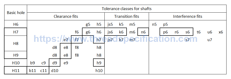
Figure 5: Preferable fits of the hole-basis system
Hole-basic fit system:
- Clearance fits: H6/g5, H6/h5, H7/f6, H7/g6, H7/h6, H8/e7, H8/f7, H8/h7, H8/d8, H8/e8, H8/f8, H8/h8, H9/d8, H9/e8, H9/f8, H9/h8, H10/b9, H10/c9, H10/d9, H10/e9, H10/h9, H11/b11, H11/c11, H11/d10, H11/h10.
- Transition fits: H6/js5, H6/k5, H6/m5, H7/js6, H7/k6, H7/m6, H7/n6, H8/js7, H8/k7, H8/m7.
- Interference fits: H6/n5, H6/p5, H7/p6, H7/r6, H7/s6, H7/t6, H7/u6, H7/x6, H8/s7, H8/u7.
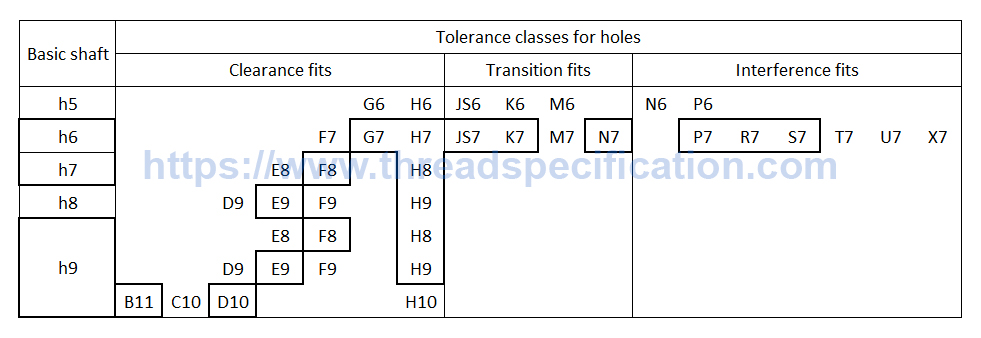
Figure 5: Preferable fits of the shaft-basis system
Shaft-basic fit system:
- Clearance fits: G6/h5, H6/h5, F7/h6, G7/h6, H7/h6, E8/h7, F8/h7, H8/h7, D9/h8, E9/h8, F9/h8, H9/h8, E8/h9, F8/h9, H8/h9, D9/h9, E9/h9, F9/h9, H9/h9, B11/h9, C10/h9, D10/h9, H10/h9.
- Transition fits: JS6/h5, K6/h5, M6/h5, JS7/h6, K7/h6, M7/h6, N7/h6.
- Interference fits: N6/h5, P6/h5, P7/h6, R7/h6, S7/h6, T7/h6, U7/h6, X7/h6.
Determination of a specific fit by calculation
In certain special functional cases, it is necessary to calculate the permissible clearances and/or interferences derived from the functional requirements of the mating parts. The clearances and/or interferences and the span of the fit obtained from that calculation have to be transformed into limit deviations and if possible into tolerance classes.
Hole & Shaft Tolerances Lookup Tool
Hole Tolerance (mm)
0.000
0.000
0.000
Standard tolerance class
Standard hole tolerance class
Synoptic representation of tolerance classes for holes for basic sizes less than or equal to 500 mm
- Position A: A9, A10, A11, A12, A13
- Position B: B8, B9, B10, B11, B12, B13
- Position C: C8, C9, C10, C11, C12, C13
- Position CD: CD6, CD7, CD8, CD9, CD10
- Position D: D6, D7, D8, D9, D10, D11, D12, D13
- Position E: E5, E6, E7, E8, E9, E10
- Position EF: EF3, EF4, EF5, EF6, EF7, EF8, EF9, EF10
- Position F: F3, F4, F5, F6, F7, F8, F9, F10
- Position FG: FG3, FG4, FG5, FG6, FG7, FG8, FG9, FG10
- Position G: G3, G4, G5, G6, G7, G8, G9, G10
- Position H: H1, H2, H3, H4, H5, H6, H7, H8, H9, H10, H11, H12, H13, H14, H15, H16, H17, H18
- Position JS: JS1, JS2, JS3, JS4, JS5, JS6, JS7, JS8, JS9, JS10, JS11, JS12, JS13, JS14, JS15, JSl6, JS17, JS18
- Position J: J6, J7, J8
- Position K: K3, K4, K5, K6, K7, K8, K9, K10
- Position M: M3, M4, M5, M6, M7, M8, M9, M10
- Position N: N3, N4, N5, N6, N7, N8, N9, N10, N11
- Position P: P3, P4, P5, P6, P7, P8, P9, P10
- Position R: R3, R4, R5, R6, R7, R8, R9, R10
- Position S: S3, S4, S5, S6, S7, S8, S9, S10
- Position T: T5, T6, T7, T8
- Position U: U5, U6, U7, U8, U9, U10
- Position V: V5, V6, V7, V8
- Position X: X5, X6, X7, X8, X9, X10
- Position Y: Y6, Y7, Y8, Y9, Y10
- Position Z: Z6, Z7, Z8, Z9, Z10, Z11
- Position ZA: ZA6, ZA7, ZA8, ZA9, ZA10, ZA11
- Position ZB: ZB7, ZB8, ZB9, ZB10, ZB11
- Position ZC: ZC7, ZC8, ZC9, ZC10, ZC11
Synoptic representation of tolerance classes for holes for basic sizes greater than 500 mm and less than or equal to 3150 mm
- Position D: D6, D7, D8, D9, D10, D11, D12, D13
- Position E: E6, E7, E8, E9, E10
- Position F: F6, F7, F8, F9
- Position G: G6, G7, G8
- Position H: H1, H2, H3, H4, H5, H6, H7, H8, H9, H10, H11, H12, H13, H14, H15, H16, H17, H18
- Position JS: JS1, JS2, JS3, JS4, JS5, JS6, JS7, JS8, JS9, JS10, JS11, JS12, JS13, JS14, JS15, JS16, JS17, JS18
- Position K: K6, K7, K8
- Position M: M6, M7, M8
- Position N: N6, N7, N8, N9
- Position P: P6, P7, P8, P9
- Position R: R6, R7, R8
- Position S: S6, S7, S8
- Position T: T6, T7, T8
- Position U: U6, U7, U8
Standard shaft tolerance class
Synoptic representation of tolerance classes for shafts for basic sizes less than or equal to 500 mm
- Position a: a9, a10, a11, a12, a13
- Position b: b9, b10, b11, b12, b13
- Position c: c8, c9, c10, c11, c12
- Position cd: cd5, cd6, cd7, cd8, cd9, cd10
- Position d: d5, d6, d7, d8, d9, d10, d11, d12, d13
- Position e: e5, e6, e7, e8, e9, e10
- Position ef: ef3, ef4, ef5, ef6, ef7, ef8, ef9, ef10
- Position f: f3, f4, f5, f6, f7, f8, f9, f10
- Position fg: fg3, fg4, fg5, fg6, fg7, fg8, fg9, fg10
- Position g: g3, g4, g5, g6, g7, g8, g9, g10
- Position h: h1, h2, h3, h4, h5, h6, h7, h8, h9, h10, h11, h12, h13, h14, h15, h16, h17, h18
- Position js: js1, js2, js3, js4, js5, js6, js7, js8, js9, js10, js11, js12, js13, js14, js15, js16, js17, js18
- Position j: j5, j6, j7, j8
- Position k: k3, k4, k5, k6, k7, k8, k9, k10, k11, k12, k13
- Position m: m3, m4, m5, m6, m7, m8, m9
- Position n: n3, n4, n5, n6, n7, n8, n9
- Position p: p3, p4, P5, P6, P7, p8, P9, P10
- Position r: r3, r4, r5, r6, r7, r8, r9, r10
- Position s: s3, s4, s5, s6, s7, s8, s9, s10
- Position t: t5, t6, t7, t8
- Position u: u5, u6, u7, u8, u9
- Position v: v5, v6, v7, v8
- Position x: x5, x6, x7, x8, x9, x10
- Position y: y6, y7, y8, y9, y10
- Position z: z6, z7, z8, z9, z10, z11
- Position za: za6, za7, za8, za9, za10, za11
- Position zb: zb7, zb8, zb9, zb10, zb11
- Position zc: zc7, zc8, zc9, zc10, zc11
Synoptic representation of tolerance classes for shafts for basic sizes greater than 500 mm and less than or equal to 3150 mm
- Position d: d7, d8, d9, d10, d11
- Position e: e6, e7, e8, e9, e10
- Position f: f6, f7, f8, f9
- Position g: g6, g7, g8
- Position h: h1, h2, h3, h4, h5, h6, h7, h8, h9, h10, h11, h12, h13, h14, h15, h16, h17, h18
- Position js: js1, js2, js3, js4, js5, js6, js5, js7, js8, js9, js10, js11, js12, js13, js14, js15, js16, js17, js18
- Position k: k6, k7, k8, k9, k10, k11, k12, k13
- Position m: m6, m7
- Position n: n6, n7
- Position p p6, p7, p8
- Position r: r6, r7, r8
- Position s: s6, s7, s8
- Position t: t6, t7
- Position u: u6, u7, u8