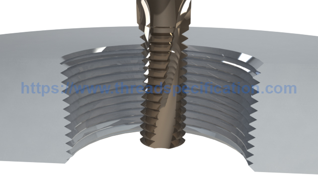
Thread milling
Thread milling produces threads with the circular ramping movement of a rotating tool. The lateral movement of the tool in one revolution creates the thread pitch. Although not as widely used as thread turning, thread milling achieves high productivity in certain applications. Thread milling should always be the application of choice when:
- Machining asymmetric/non-rotating components.
- Machining materials that cause chip breaking and chip evacuation problems.
- Machining tough materials that create high cutting forces.
- Machining against a shoulder or close to the bottom of a blind hole.
- Machining thin-walled components.
- Component set-ups are unstable.
- Tool inventory needs to be minimized.
- You do not want to risk tap breakage on expensive parts – thread mills can always be removed from the component completely.
- A machine tool capable of simultaneous movement in the X, Y and Z-axis directions is required.
Up Milling and Down Milling
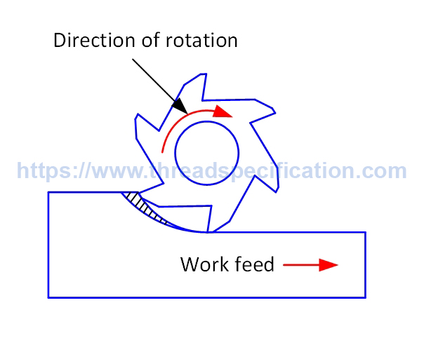
Up milling
In UP Milling to perform the operation the cutter and feed moves opposite to each other.
It is also called a Conventional Milling.
The cutting edge has to be forced into the cut, creating a rubbing or burnishing effect with friction, high temperatures, and often contact with a work-hardened surface caused by the preceding edge. All this shortens tool life.
Thick chips on exit from cut will reduce tool life.
The large thickness and higher temperature at exit will sometimes stick or weld the chips to the cutting edge and carry them around to the start of the next cut or cause edge frittering momentarily.
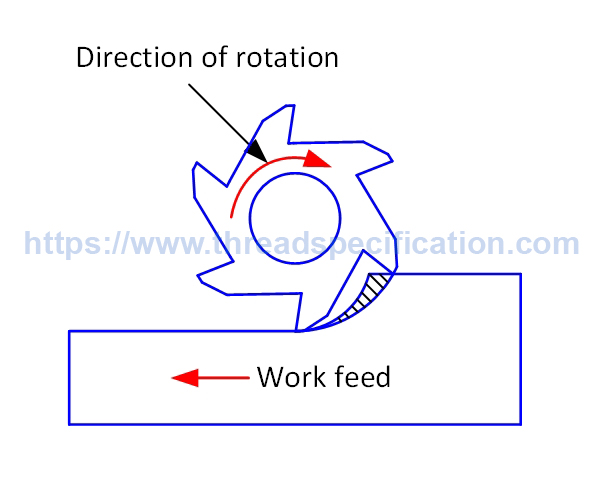
Down milling
In Down Milling to perform the operation the cutter and feed move in the same direction with each other.
It is also called a Climb Milling.
Down-milling is always the preferred method—when machine tool, fixture, and workpiece will allow.
Chip thickness decreases from the start of cut, until reaching zero at the end, which stops the edge from rubbing and burning against the surface before it is engaged into cut.
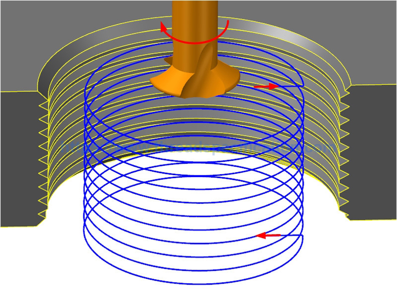
Thread milling toolpath
Thread milling tool path will give right or left-hand threads, using down-milling or up-milling. Thread milling requires machine tools which are capable of simultaneous movements on the X, Y, and Z axes. The thread diameter is determined by the X and Y axis, while pitch is controlled by the Z axis.
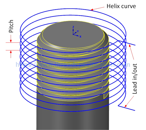
Basically, the thread milling tool path contains three parts: lead in, lead out and helix curve. The pitch of the helix is equal to the pitch of the thread. The direction of the helix (CW, CCW) will determine the left-hand or right-hand thread. The diameter of the helix is calculated by the diameter of the cutting tool and the diameter of the thread.
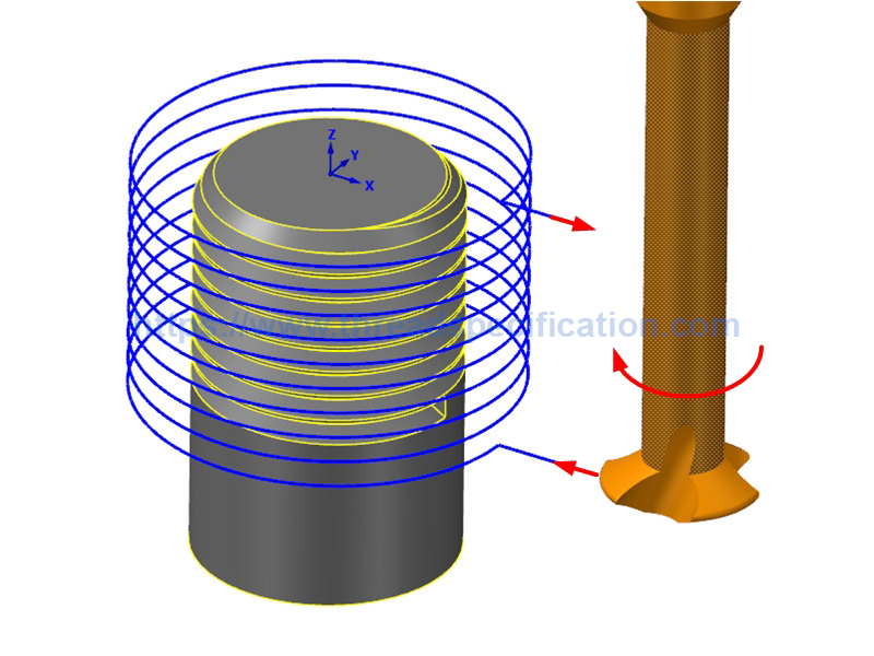
External right-hand thread
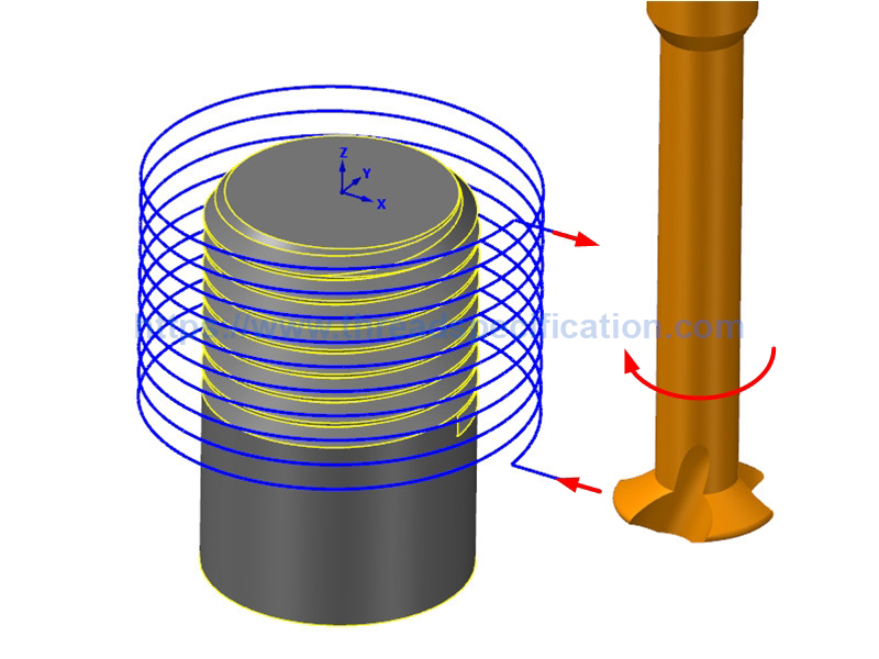
Up Milling
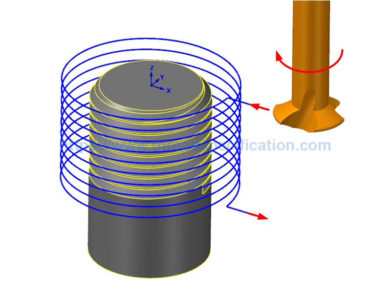
Down Milling
External left-hand thread
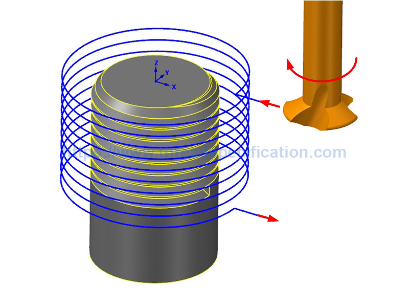
Up Milling
Down Milling
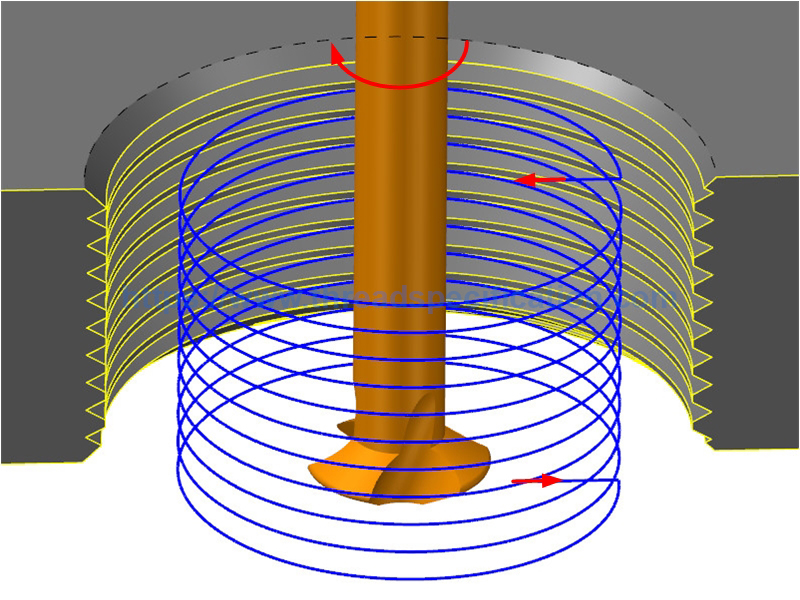
Internal right-hand thread
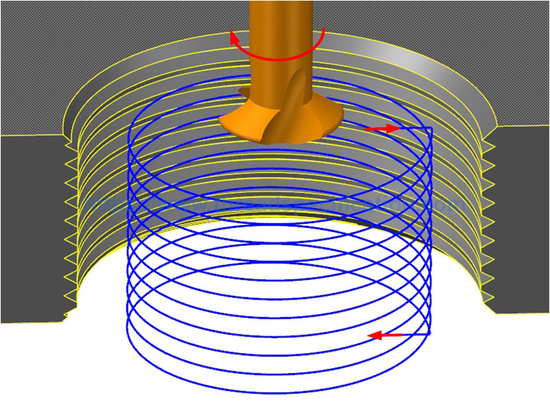
Up Milling
Down Milling
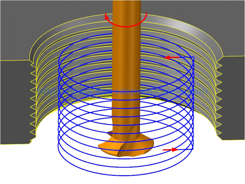
Internal left-hand thread
Up Milling
Down Milling
How to create the toolpath for the single point thread milling tool
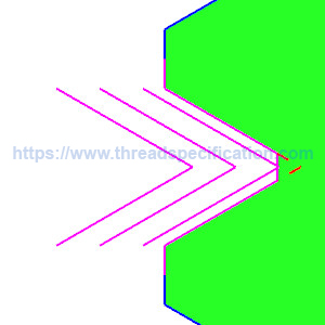
First, to create the tool path for the single point thread milling tool, we must know the tool’s profile. The single point tool’s profile is as in the following drawing.
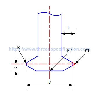
- D: tool diameter
- P1: cutting point
- P2: tool tip point
- t: distance from cutting point to tool tip point
- R: tool radius
- L: cutting length, must greater than height of fundamental triangle
Next, search for the thread specifications on our site and download the thread’s profile dxf. For internal thread, the profile dxf is the valley form of the thread, and for external thread, the profile dxf is the thread top form. So, for the external thread, we copy the thread form to create the valley form of the thread.
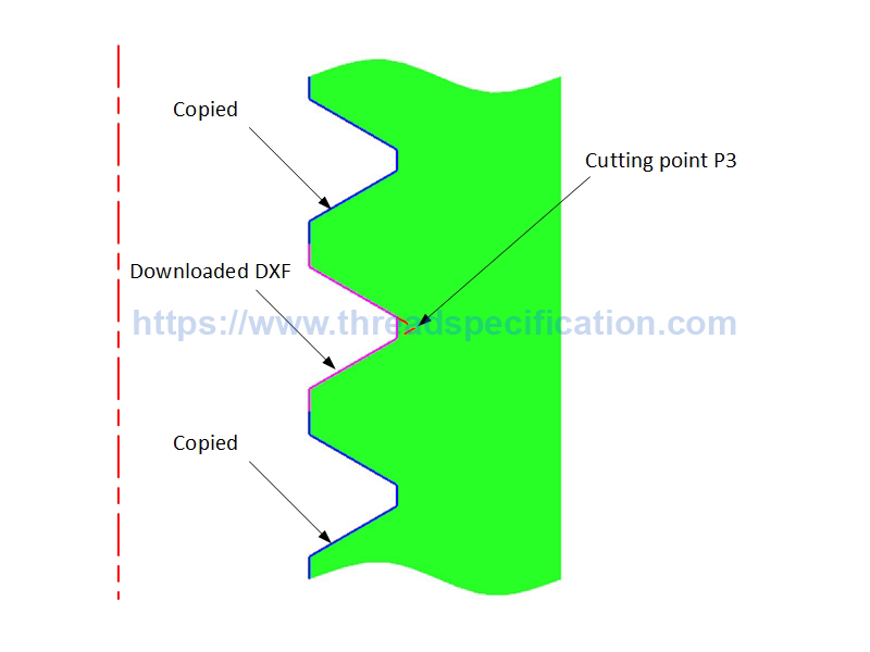
Internal Thread
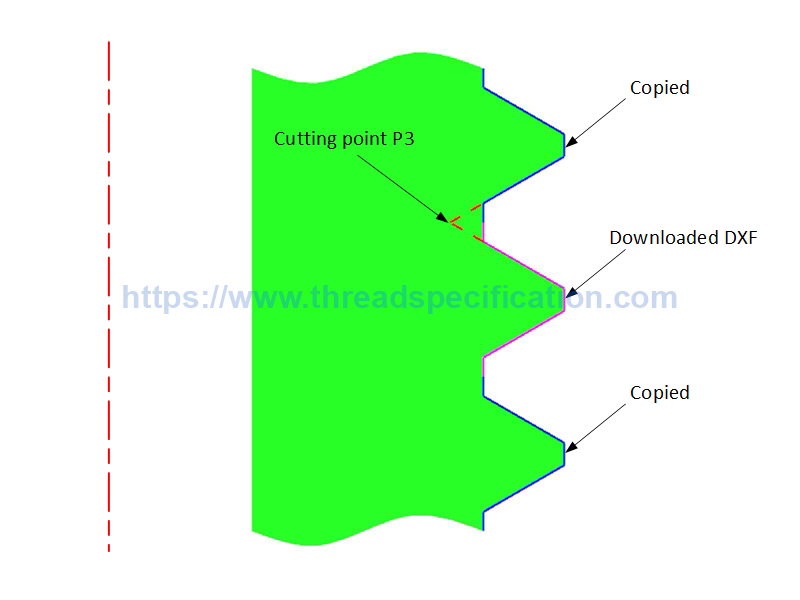
External Thread
Making the cutting point of the tool coincide with the cutting point of the thread, we will get the diameter of the helix curve.
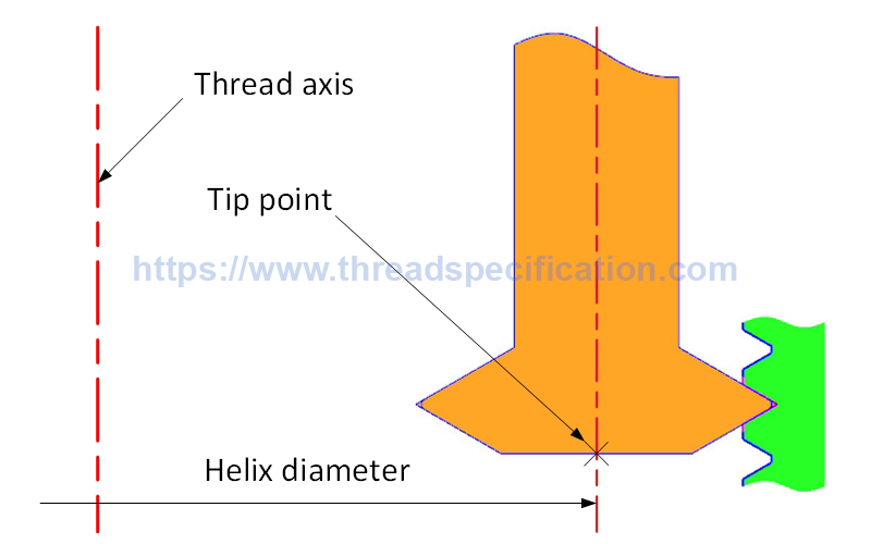
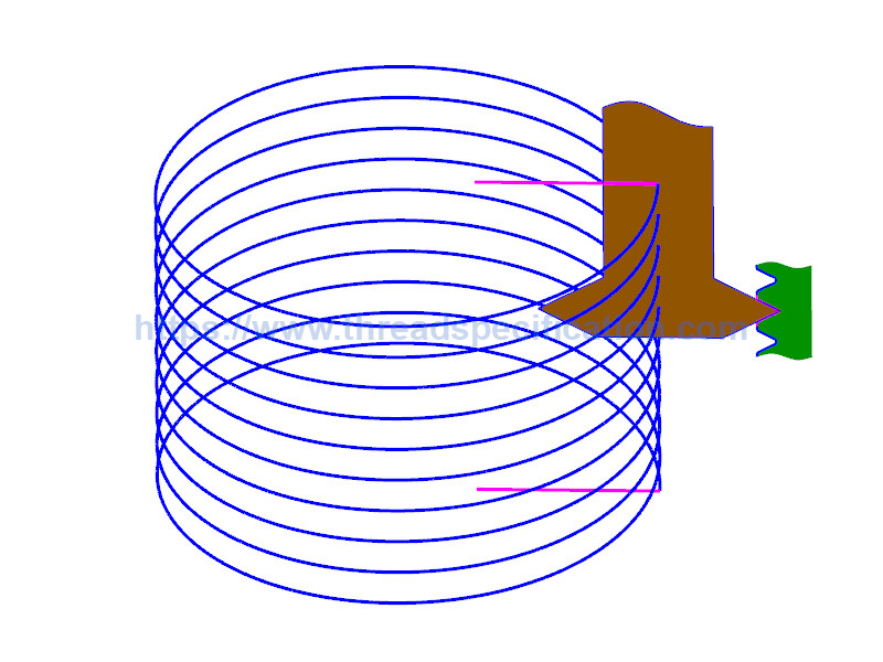
From the tip point of the tool we create the helix curve with this diameter. The pitch and the taper rate of the helix are the same with the thread. The direction of the helix is based on the right-hand or left-hand of the thread.
The length of the helix is calculated by the effective length of the thread plus the distance from the cutting point to the tip point of the tool (t) and plus half of the pitch.
Helix length = effective length + t + 1/2 pitch.
Finally we add lead-in and lead-out lines to the top and bottom of the helix. The lead in/out length should be greater than height of fundamental triangle.
To create multiple tool paths, we just move the thread profile and follow those above steps to create the helix curve and lead in/out.