How to create a 3D model of taper thread in 3D CAD software
In this article, we discuss the method for creating a 3D model of a taper thread. In common, there are five steps to creating a 3D model for a taper thread:
- Step 1: Search for the thread specifications.
- Step 2: Create a 1 in 16 taper rate shaft whose diameter at the gauge plane is equal to the major diameter of the thread.
- Step 3: Create the thread profile at the gauge plane that uses the shaft’s axis as the thread axis.
- Step 4: Create the helix, which has the same pitch as the thread, and the taper rate is 1 in 16.
- Step 5: Create the “Swept Cut” function to cut the material of the shaft to create the 3D model of the thread.
Let’s continue with the example of an external national pipe thread, NPT 1/16.
Step 1: Search for the thread specification
First, we need the dimensions of the external national pipe thread, NPT 1/16. Read this article, “How to Create a Taper Thread Profile with CAD Software“, to know how to search for thread dimensions using this website. We got the information for the external national pipe thread, NPT 1/16, as below:
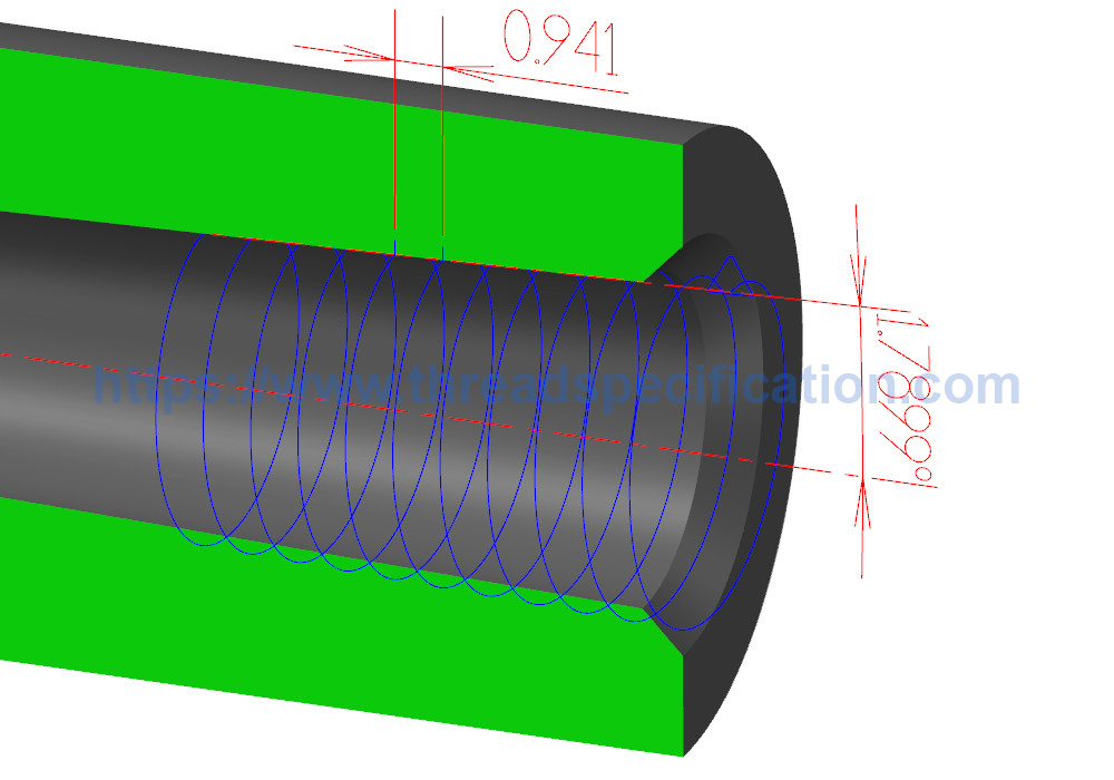
- Pitch P = 0.941 mm
- Engagement length: L1 = 4.064 mm
- Effective thread length: L2 = 6.632 mm
- Average major diameter d = 7.8355 mm
- Average minor diameter d1 = 6.4485 mm
- Average minor diameter d1 = 7.142 mm
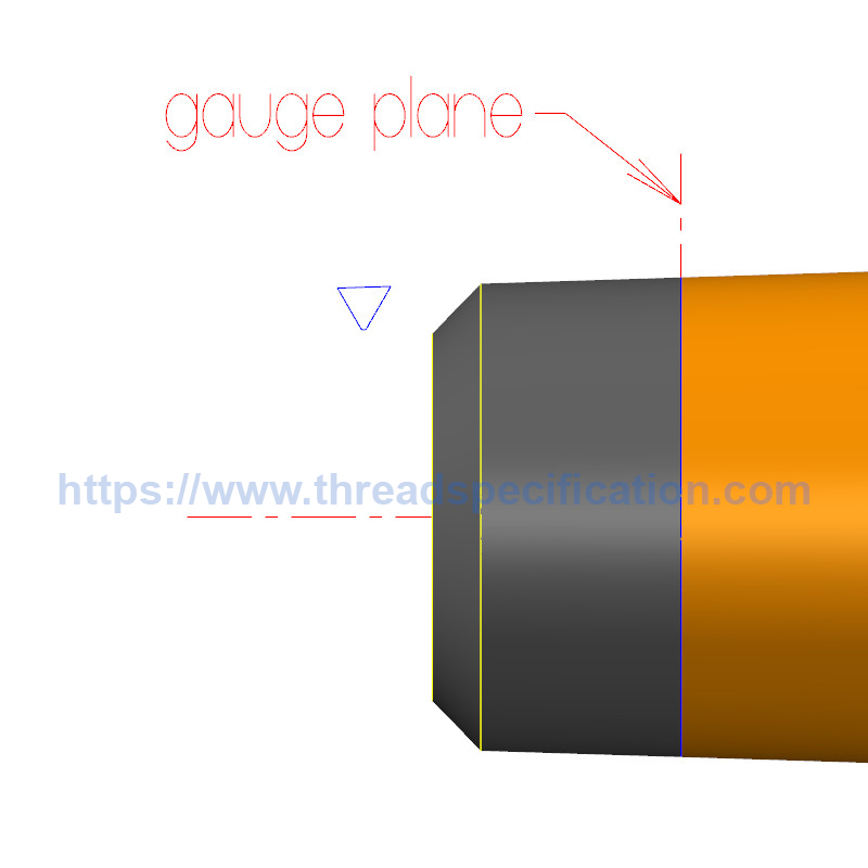
Step 2: Create a 1 in 16 taper rate shaft whose diameter at the gauge plane is equal to the major diameter of the thread
First, we change taper rate of 1 in 16 into angle. The angle is calculated by this formula: arctan(1/16)/2, it is nearly 1.7899 degree.
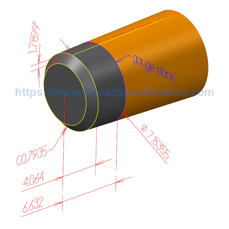
From the gauge plane (wherever you want), we make a shaft with a diameter equal to the thread’s major diameter, which is 7.8355 mm, and the draft angle of the shaft is 1.7899 degree. The shaft consists of two parts: one part goes smaller at the end and has the length equal to L1, that is, 4.064 mm; the other part is on the opposite site; it goes bigger at the end and has the length greater than (L2 – L1), that is, 6.632 – 4.064 = 2.568 mm.
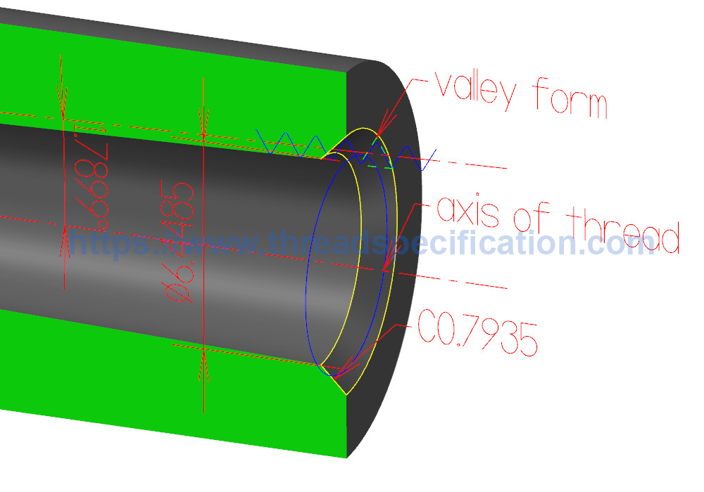
We also add a chamfer to the shaft end on the L1 side; this chamfer is used to remove the burr at the start of the thread. The size of the chamfer can be calculated using this formula: C = (major diameter – minor diameter)/2 + tolerance. Let’s say the tolerance is 0.1 mm; the chamfer value will be C = (7.8355 – 6.4485)/2 + 0.1 = 0.7935 mm.
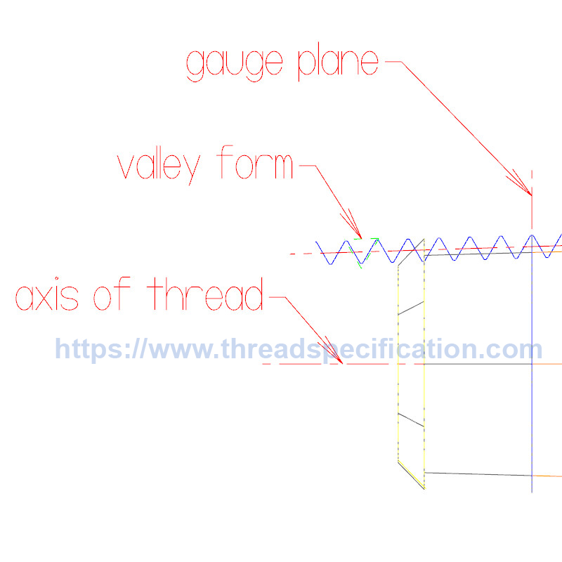
Step 3: Create the thread profile at the gauge plane that uses the shaft’s axis as the thread axis
Follow the instructions in this article, “How to Create a Taper Thread Profile with CAD Software“, to create a thread profile for the external national pipe thread NPT 1/16. Use the axis of the shaft as the axis of the thread and the gauge plane of profile is the gauge plane of the shaft.
For the external thread, the basic form of the thread is the top of the thread (male shape), so we will use the bottom of the thread or valley form of the thread (female shape) to create the basic valley profile for the “Swept Cut” function. Just choose a valley outside the shaft, trim unnecessary lines from the thread profile, and we have the basic valley profile.
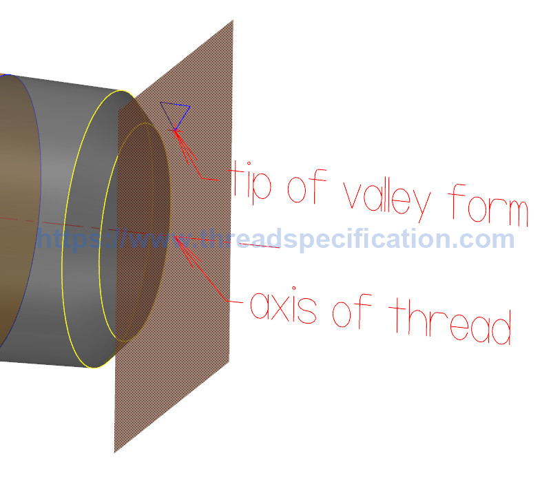
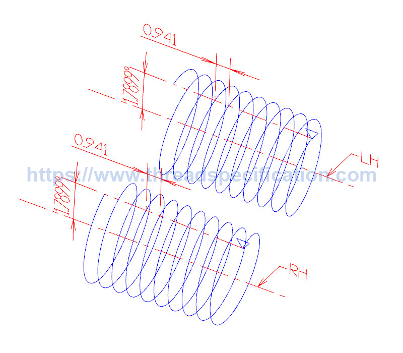
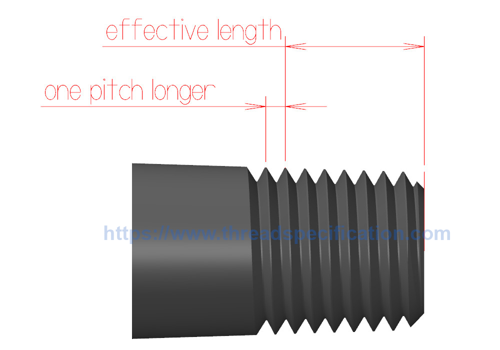
Step 4: Create the helix, which has the same pitch as the thread, and the taper rate is 1 in 16
Create a plane such that the normal vector is the axis of the shaft and goes through the tip of the basic valley profile. Use this plane to create the helix curve. At that plane, the basic diameter of the helix equals the minor diameter of the thread, the pitch of the helix is the pitch of the thread, and the draft angle is 1.7899 degree. The length of the helix is determined by the effective length of the thread (L2). The length of the helix should be one pitch longer than the effective length of the thread. And the direction of the helix is determined by the right- or left-hand thread.
Step 5: Create the “Swept Cut” function to cut the material of the shaft to create the 3D model of the thread
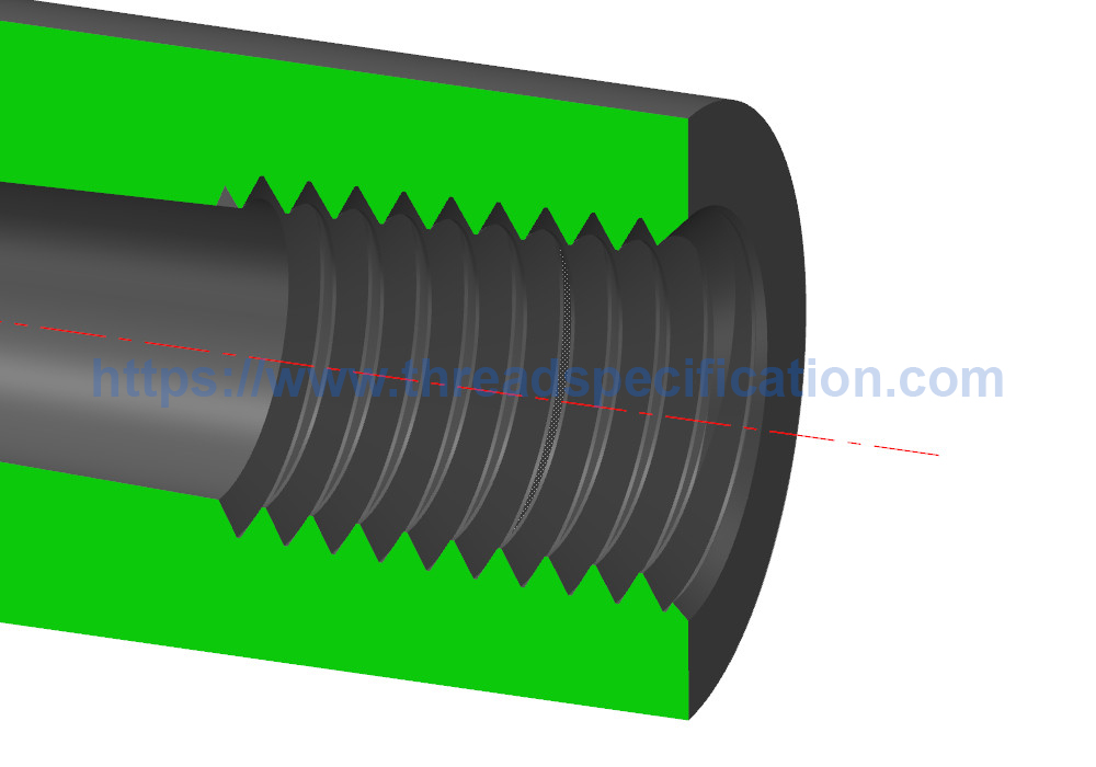
After we have the basic valley profile and the helix as the path, use the “Swept Cut” function to remove material from the shaft to create the 3D model of the external national pipe thread NPT 1/16. Some 3D CAD software doesn’t have the “Swept Cut” function; at that time, we will create a “Swept” function to create the shape of the valley, then use “Boolean Subtract” to subtract the shape of the shaft from the shape of the valley, and we will have the 3D model of the thread.
The way to create the 3D model for internal taper threads is the same as with external threads. For internal threads, the basic profile of the thread will be the valley profile or bottom profile of the thread (female shape); use it as the basic valley profile.
Here is an example of creating a 3D model for the internal national pipe thread, NPT 1/16. We search for the specifications listed below:
- Pitch P = 0.941 mm
- Engagement length: L1 = 4.064 mm
- Wrench makeup length: L3 = 2.822 mm
- Average major diameter D = 7.8355 mm
- Average minor diameter D1 = 6.4485 mm
- Average pitch diameter D2 = 7.142 mm
First, create a hole such that the diameter at the gauge plane is equal to the minor diameter of the thread, which is 6.4485 mm, and the draft angle of the hole is 1.7899 degrees. The gauge plane of the internal pipe thread is at the start of the hole (on the bigger side). We also add a chamfer to the hole; the size of the chamfer is C = (7.8355 – 6.4485)/2 + 0.1 = 0.7935. The effective length of the internal national pipe thread is L1 plus L3, which is (4.064 + 2.822) = 6.886 mm. Next, create the thread profile and the helix. The length of the helix should be one pitch longer than the effective length of the thread. Finally, use the “swept cut” function to create the thread shape.